
Controls
Monitor, measure, adjust
The control system of an air handling unit monitors and maintains indoor comfort conditions by adjusting the amount of heat, cooling and fresh air brought into the building.
It relies on sensors that measure temperature, humidity and air quality, indoors as well as outdoors. This data is sent to a controller that adjusts the unit’s settings accordingly to maintain the desired conditions.
These controls can be implemented on a new unitdesigned to the latest standards, as well as on existing units as part of a retrofitto optimise performance.

An expert, independent partner
We put our expertise and know-how at our customers’ service to offer solutions matched to their needs and their budget. Asindependent expertswe select the best equipment to meet their objectives, whatever they may be, with integrated systems that guarantee optimal energy performance and comply with the applicable standards.
Example of a basic visualisation
Climatix visualisation of an air handling unit: plant schematic and HMI control screen.


Integrated control solutions
Depair Climatix
Controls integrated into the AHU (Climatix as standard), for precise management of temperature, humidity and air quality.
Depair Connect
Remote management and remote monitoring, compatible with BACnet & KBOB to integrate with the building’s BMS.
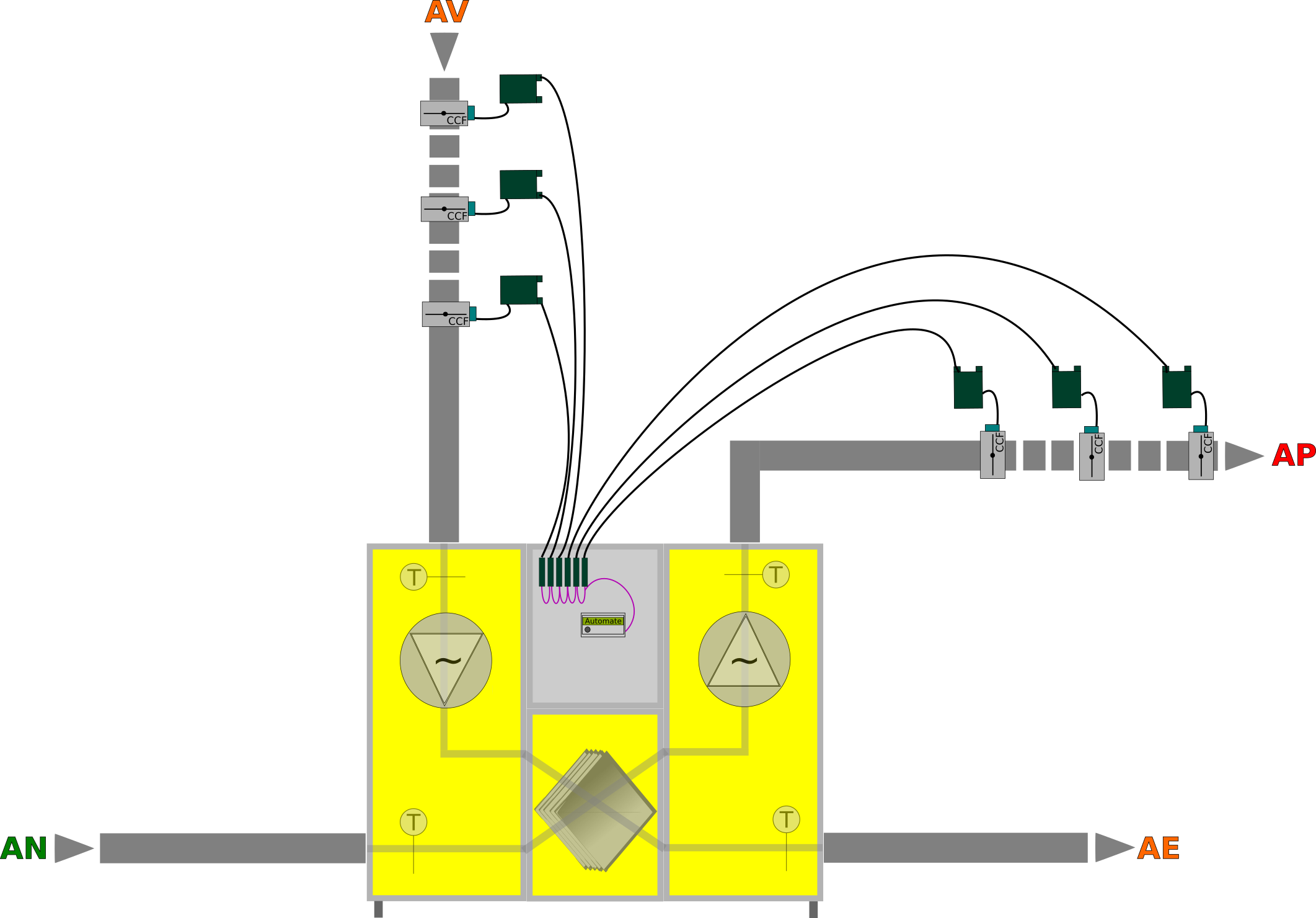
THC24 / SOC24 wiring
Standardised wiring solutions for fast, reliable connection of control peripherals.
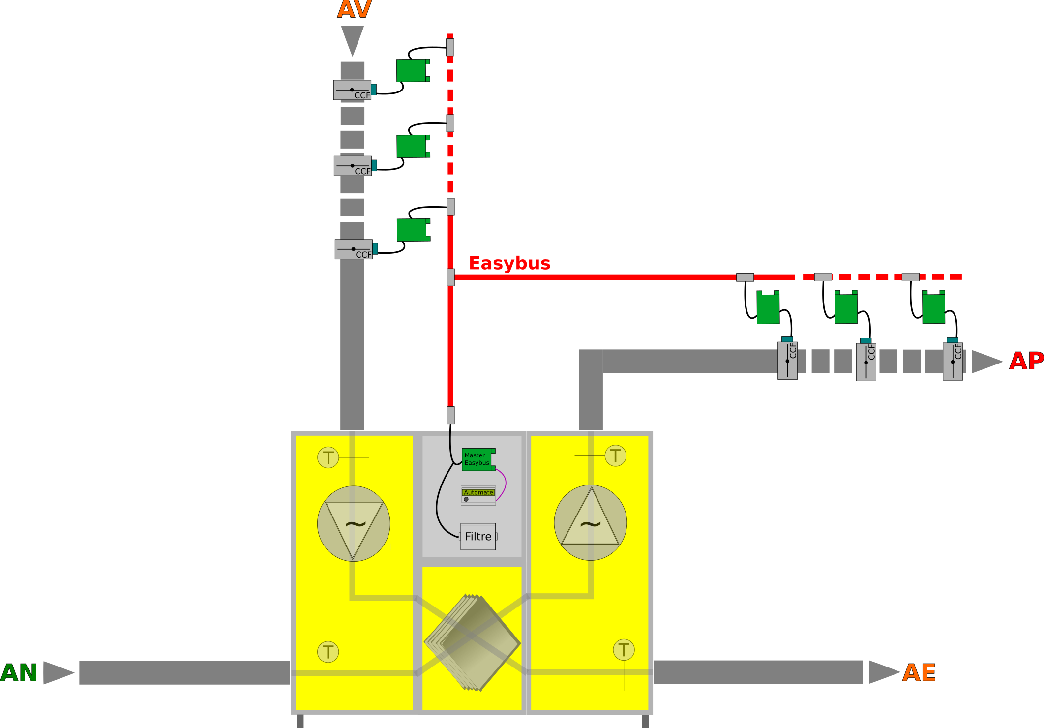
EasyBus3: VAV
Variable air volume: airflow adapted to requirements, with up to 256 VAV controllers and 256 sensors on a single line.
Connected junction boxes
An automated system that simplifies wiring and makes commissioning more reliable.
Fire damper wiring
Management of fire dampers according to the configuration, with or without the EasyBus system.
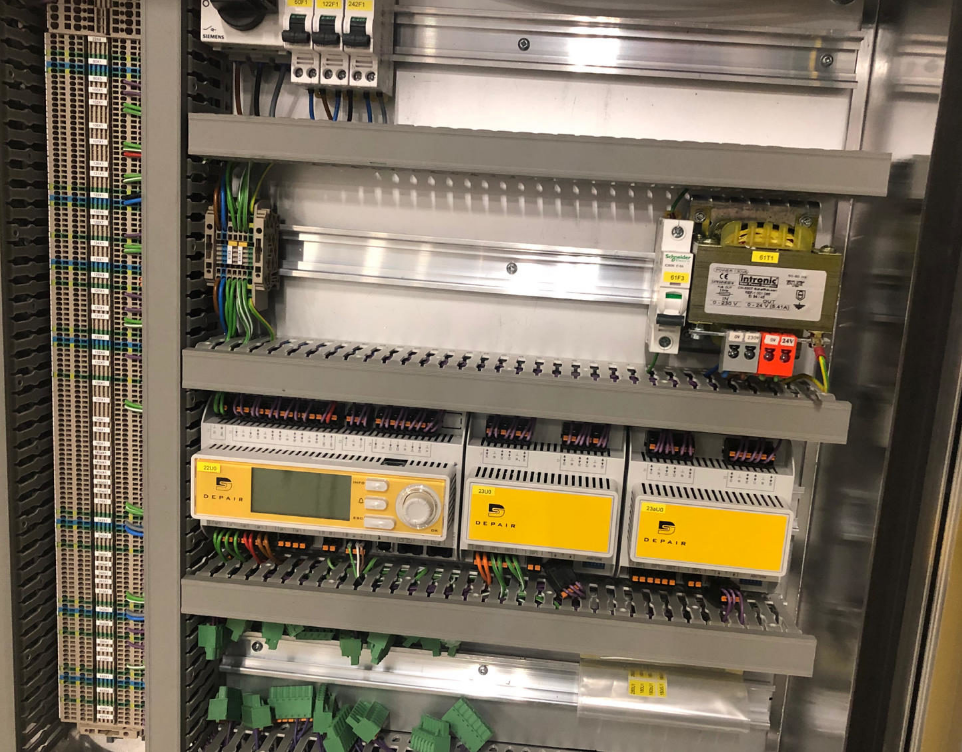
Panels designed, wired and tested by Depair
Every control panel is built entirely by Depair: designed by our engineering office together with the air handling unit, wired and tested in our workshop, then delivered pre-wired on the unit.
Design and drawings
Wiring diagrams, bill of materials, terminal and cable labelling, drawn up with the unit design and handed over with the project file.
Built to SN EN 61439
Panels built to SN EN 61439-1/-2, from the choice of protection devices to the wiring.
Workshop testing
Routine tests and functional check before delivery, recorded in a test report.
Pre-wired on the AHU
The panel is mounted and connected on the unit in the factory, which cuts on-site connection work accordingly.


Matching airflow to actual requirements
The EasyBus3® system uses signals transmitted through the electrical cables to remotely control the building’s various ventilation devices. Variable air volume (VAV) allows the airflow to be adapted to specific requirements, for better management of comfort and efficiency.
The Easy3-V module drives two variable flow controllers (24 VDC / 0-10 V) and measures two 0-10 V signals, for example a supply VAV and an extract VAV, while measuring air quality and temperature via a combined sensor.
Up to 256 VAV controllers and 256 0-10 V sensors can be connected on a single EasyBus3 line, offering great flexibility and considerable capacity for expansion.
Six key steps to a reliable AHU
Initial checks
Checking that all parts of the AHU are correctly installed, that the electrical connections are safe and that the filters are clean.
Start-up
Powering up (by an electrician) and checking that all components work correctly: fans, valves, temperature controllers, etc.
Parameter settings
Adjusting the AHU settings to the building’s requirements and the manufacturer’s specifications.
Final checks
Checking pressure and airflow, and testing the whole system to make sure it performs as intended.
Documentation & training
Documenting every commissioning step and training staff where required.
Ongoing maintenance
Drawing up a regular maintenance plan to guarantee correct operation throughout the life cycle.
OIBT Art. 24, electrical safety
Swiss Ordinance on Low Voltage Electrical Installations. An initial inspection must be carried out before an installation (or parts of it) is commissioned, in parallel with construction, and recorded in a report:
- the electrical installation is free of safety-related defects;
- it complies with the safety requirements of standard NIBT 6.1;
- during a partial commissioning, the cables of peripherals not yet available must under no circumstances be connected to the terminal block of the switchgear assembly.
Control documents
User guides and parameters (PDF).
Need bespoke controls?
Climatix, Depair Connect, EasyBus3 VAV, BACnet/KBOB: from a new AHU to a retrofit, we design the control system suited to your building.
Contact us